Parallel Flow Heat Exchanger
Introduction
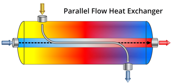
Parallel flow heat exchangers in air handling units (AHUs) enable energy-efficient heat recovery by transferring thermal energy between incoming fresh air and outgoing exhaust air streams flowing in the same direction.
A parallel-flow heat exchanger is one where both fluids enter the exchanger at the same end and flow in the same direction along its length.
In an AHU, the two fluids are usually:
- Air (supply or return air), and
- Water or refrigerant (chilled water, hot water, or refrigerant inside the coil).
Configuration
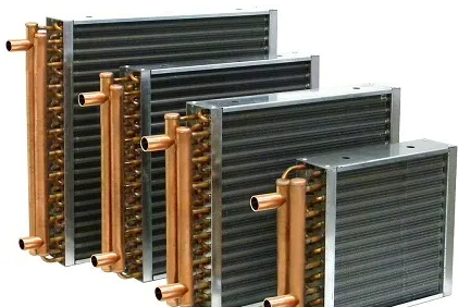
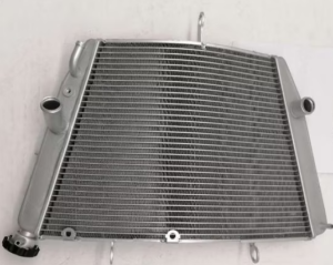
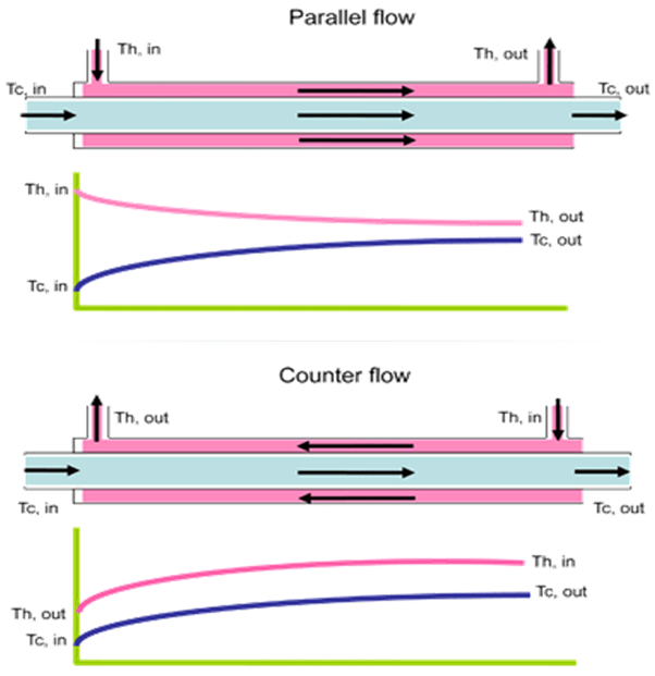
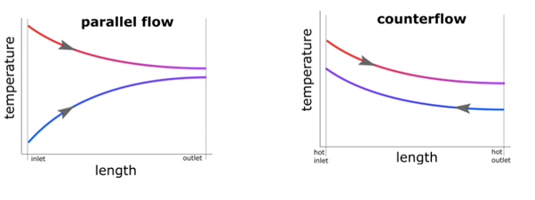
In this setup, both air streams—typically warm exhaust air and cooler supply air—move parallel through separate channels or plates within a compact exchanger core, often made of thin metal plates or membranes. Heat transfers from the hotter stream to the cooler one across the separating surface without mixing the airstreams. This contrasts with counter-flow designs where streams move oppositely for higher efficiency.
Application in AHU's
AHUs use these exchangers primarily for ventilation heat recovery in commercial buildings, reducing heating or cooling loads by preconditioning incoming air. They suit moderate-efficiency needs where space limits counter-flow options, common in HVAC systems for offices or industrial setups like concrete plants needing consistent air quality.
They are commonly used in:
- Pre-heating coils
- Pre-cooling coils
- Small to medium AHUs
Systems where rapid temperature change at the air inlet is desired
Performance Traits
Efficiency typically ranges 40-60% for temperature recovery, lower than cross-flow or rotary types due to diminishing temperature gradients along the flow path. Benefits include simple construction, low pressure drop, and frost resistance in mild climates; drawbacks involve reduced effectiveness over length as streams approach equilibrium. Real-world studies show annual heat recovery savings up to 25 MWh in monitored units.
Working
- Air enters the coil at the same side where the heating/cooling fluid enters.
- At the inlet, the temperature difference is maximum, so heat transfer is very high initially.
- As both fluids move together:
- Their temperatures approach each other
- The rate of heat transfer decreases toward the outlet
- Both fluids leave the coil from the same end.
Temperature Profile (Simple View)
- For a cooling coil:
- Inlet:
- Hot air + cold chilled water → strong cooling
- Outlet:
- Cooler air + warmer water → reduced heat transfer
- For a heating coil:
- Inlet:
- Cold air + hot water → strong heating
- Outlet:
- Warmer air + cooler water
Parallel-Flow Vs Counter-Flow (Quick Comparison)
|
Feature |
Parallel Flow |
Counter Flow |
|
Flow direction |
Same direction |
Opposite direction |
|
Initial heat transfer |
Very high |
Moderate |
|
Overall efficiency |
Lower |
Higher |
|
AHU application |
Simple & compact systems |
High-performance systems |